On the File tab, select New, and then search for Engineering templates. The template opens an unscaled drawing page in portrait orientation. Drag electrical component shapes onto the. . Use the Electrical Engineering drawing type in Visio Professional or Visio Plan 2 to create electrical and electronic schematic diagrams. It's often much easier to convey information with a well-designed diagram than to communicate through a large text blurb. I'll guide you through the process of creating custom shapes, using developer mode in Visio, and building your o. Below, we'll go over the basics of creating diagrams in Visio, the specifics of creating schematic drawings for electrical installations, and. . Visio is a diagraming tool that makes it easy and intuitive to create flowcharts, diagrams, org charts, floor plans, engineering designs, and more by using modern templates with the familiar Office experience.
[PDF Version]
Figure 1 shows a microgrid schematic diagram. The microgrid encompasses a portion of an electric power distribution system that is located downstream of the distribution substation, and it includes a variety of DER units and different types of end users of electricity and/or heat. . Presentation was intended to build foundational understanding of energy resilience, reliability, and microgrids. Coalition stakeholders include the City of Oakridge, South Willamette Solutions, Lane County, Oakridge Westfir Area Chamber of Commerce, Good Company/Parametrix, Oakridge Trails. . Microgrids as the main building blocks of smart grids are small scale power systems that facilitate the effective integration of distributed energy resources (DERs). DER units include. . and (c) distribution management system.
[PDF Version]
This article provides an overview of the existing microgrid controls, highlights the impor-tance of power and energy management strategies, and describes potential approaches for mar-ket participation. Figure 1 shows a microgrid schematic diagram. . Microgrids are localized electrical grids with specific boundaries that function as single controllable entities. This. . Authorized by Section 40101(d) of the Bipartisan Infrastructure Law (BIL), the Grid Resilience State and Tribal Formula Grants program is designed to strengthen and modernize America's power grid against wildfires, extreme weather, and other natural disasters that are exacerbated by the climate. . Microgrids as the main building blocks of smart grids are small scale power systems that facilitate the effective integration of distributed energy resources (DERs). ES is connected to the DC sub-g nd operation strategies for the DC microg n technology to construct a microgrid system. Department of Energy (DOE), operated under Contract No. Funding provided by the DOE's Communities LEAP (Local Energy Action Program) Pilot.
[PDF Version]
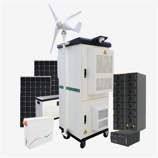
This article will provide a comprehensive guide on how to properly connect solar panels in parallel, along with a detailed diagram to help you visualize the process. First and foremost, it is important to understand the basics of parallel connection. . Compared to the schematic diagrams of most cutting-edge technological devices, solar panel wiring diagrams are actually remarkably simple. Let's explore the key factors that will help you make the right choice. When solar panels are connected in parallel, the. . To do it right, you have to devote a lot of time and forethought into how it will come together. This solar system wiring diagram depicts an off-gr d scenario where the solar panels are arge controllers, batteries, and e or service panel requires. .
[PDF Version]
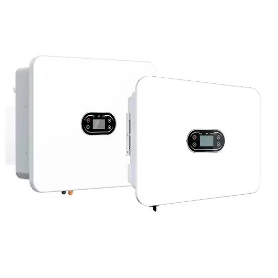
In this article, I will explain how to connect a solar panel to a battery step-by-step. I will also share a few tips you need to know along the way. This prevents controller damage and ensures proper system voltage detection, as charge controllers use battery voltage as their reference point. Here is a diagram connecting a single 100W solar panel to a 12V 100Ah lithium battery and a 500W inverter: In the first step, you will wire the. . This diagram outlines the necessary connections between the panels, batteries, and other components to ensure a properly functioning system. The PV solar panel wiring diagram provides a visual representation of the electrical circuit for your solar panel system. Not only does it decrease. . Solar panels generate electricity from sunlight, and this energy can be stored in batteries for later use.
[PDF Version]
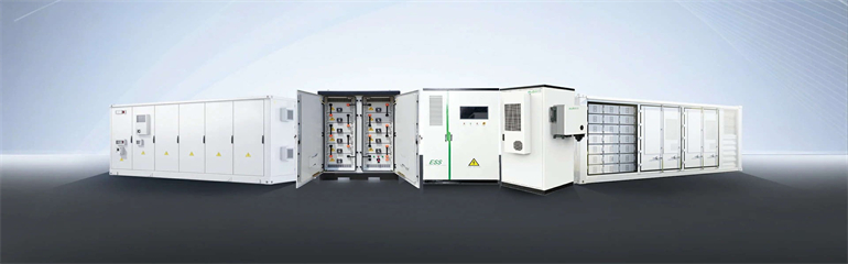
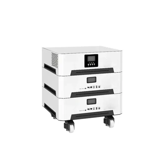
In this comprehensive guide, we will dissect the components of a battery energy storage system diagram, explore the differences between AC and DC coupling, and help you identify the right configuration for your commercial or residential needs. What is a Battery. . Electrochemical: Storage of electricity in batteries or supercapacitors utilizing various materials for anode, cathode, electrode and electrolyte. Typically, pumped storage hydropower or compressed air energy storage (CAES) or flywheel. Let's break down what makes these systems tick. Despite record investments in renewables, 35% of generated solar energy gets wasted during peak production hours globally [8]. Therefore, accurately grasping the characteristics of the battery and the needs of the. . ack and battery cell mass composition, by components.
[PDF Version]