On the File tab, select New, and then search for Engineering templates. The template opens an unscaled drawing page in portrait orientation. Drag electrical component shapes onto the. . Use the Electrical Engineering drawing type in Visio Professional or Visio Plan 2 to create electrical and electronic schematic diagrams. It's often much easier to convey information with a well-designed diagram than to communicate through a large text blurb. I'll guide you through the process of creating custom shapes, using developer mode in Visio, and building your o. Below, we'll go over the basics of creating diagrams in Visio, the specifics of creating schematic drawings for electrical installations, and. . Visio is a diagraming tool that makes it easy and intuitive to create flowcharts, diagrams, org charts, floor plans, engineering designs, and more by using modern templates with the familiar Office experience.
[PDF Version]
In our guide, we unpack how to wire solar panels and provide diagrams illustrating solar schematic examples for every solar setup, from residential to RV to camper van. You"ll be ready to power up your home or get. . Before diving into the splicing process, it's essential to have a basic understanding of solar PV wires. These wires are specifically designed to withstand the harsh environmental conditions typically encountered in solar installations, such as high temperatures, UV radiation, and moisture. A well-executed splice can prevent power loss, reduce the risk of electrical faults, and. . The intent of this bulletin is to clarify some of the wiring method requirements as per Section 64 Rules. This solar panel wiring guide explains different methods. . Solar panel diagrams are graphic representations of the connections you should make between each PV module and other components of the solar power system, including: Why Are They Important? Remember the saying, “Measure twice and cut once?” Detailed specifications with diagrams for reference help. . Installing a solar panel system is an efficient and sustainable way to generate electricity for your home or business. This diagram outlines the necessary connections between the. .
[PDF Version]
Figure 1 shows a microgrid schematic diagram. The microgrid encompasses a portion of an electric power distribution system that is located downstream of the distribution substation, and it includes a variety of DER units and different types of end users of electricity and/or heat. . Presentation was intended to build foundational understanding of energy resilience, reliability, and microgrids. Coalition stakeholders include the City of Oakridge, South Willamette Solutions, Lane County, Oakridge Westfir Area Chamber of Commerce, Good Company/Parametrix, Oakridge Trails. . Microgrids as the main building blocks of smart grids are small scale power systems that facilitate the effective integration of distributed energy resources (DERs). DER units include. . and (c) distribution management system.
[PDF Version]
This diagram outlines the necessary connections between the panels, batteries, and other components to ensure a properly functioning system. Most modern photovoltaic systems for residential or portable use don't actually require much “wiring. ” At least not in the. . A crucial part of this installation process is understanding the wiring diagram for your photovoltaic (PV) solar panels. The PV solar panel wiring diagram. . An effective solar panel wiring is highly essential for maximum energy output, solar power system stability and preventing power loss.
[PDF Version]
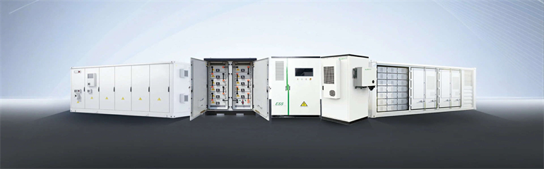
Detailed explanation of the principle of energy storage air condi apsulated slurries, thermal power and heat rejection of the absorption ms are identical as other forms of energy storage methods,as mentioned earlier. A typical thermal energy . . Thermal Energy Storage (TES) for space cooling, also known as cool storage, chill storage, or cool thermal storage, is a cost saving technique for allowing energy-intensive, electrically driven cooling equipment to be predominantly operated during off-peak hours when electricity rates are lower. Air conditioning of commercial buildings during summer daytime hours is the largest single contributor to electrical peak demand. In the. . What is energy storage and how does thermal energy storage work? Thermal energy storage is like a battery for a building's air-conditioning system. You might like: Different Types of Refrigeration & Their Working [Explained] What is Air Conditioning System? An air conditioner is an electrical device that. . An air conditioning system diagram is a visual representation of how an HVAC (Heating, Ventilation, and Air Conditioning) system works.
[PDF Version]
A practical, standards-informed guide to designing lighting layouts for municipal solar street light systems. . Theft Protection: Photovoltaic panel bolts use irregular structures, battery case welded and fixed. Through this guide, a systematic approach can be achieved from illumination requirements to economic returns. . A solar street light converts sunlight into electricity during the day and uses this stored energy to power LED luminaires at night. Modern systems use high-efficiency. . Quality manufacturers should provide two complementary 3-D simulations of your street lighting design layout--one that is desired versus one that is recommended based upon the location. Once you master that, you can size batteries and panels accurately. I will walk you through the process. . Extracting the maximum amount of power from the solar panel is difficult due to the nonlinearity and variability of the Voltage-Current (V-I) characteristic.
[PDF Version]