Figure 1 shows a microgrid schematic diagram. The microgrid encompasses a portion of an electric power distribution system that is located downstream of the distribution substation, and it includes a variety of DER units and different types of end users of electricity and/or heat. . Presentation was intended to build foundational understanding of energy resilience, reliability, and microgrids. Coalition stakeholders include the City of Oakridge, South Willamette Solutions, Lane County, Oakridge Westfir Area Chamber of Commerce, Good Company/Parametrix, Oakridge Trails. . Microgrids as the main building blocks of smart grids are small scale power systems that facilitate the effective integration of distributed energy resources (DERs). DER units include. . and (c) distribution management system.
[PDF Version]
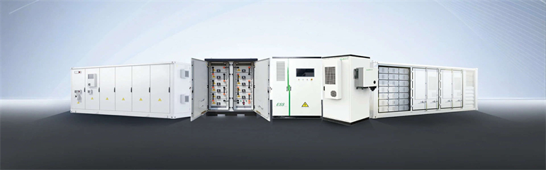
In this comprehensive guide, we will dissect the components of a battery energy storage system diagram, explore the differences between AC and DC coupling, and help you identify the right configuration for your commercial or residential needs. Today, much of the functionality is handled by an on-board computer following firmware and software instructions. . Electrical Energy Storage, EES, is one of the key technologies in the areas covered by the IEC. EES techniques have shown unique capabilities in coping with some critical characteristics of electricity, for example hourly variations in demand and price. Capacity[Ah]: The amount of electric charge the system can deliver to the onnected load while maintaining acceptabl attery energy storage system development to thrive. Energy-related carbon dioxide. .
[PDF Version]
Learn how to wire a 12V solar panel system with this straightforward wiring diagram and step-by-step guide. Always refer to the NEC code in effect or consult a licensed electrician for safety and accuracy. There are two basic approaches to connecting a grid-tied solar panel system, as shown in. . Wiring solar panels together incorrectly can lead to damaging or destroying valuable components-- it can even be life-threatening. The total output voltage and current of your array are determined by how you connect the individual PV modules to each other and to the solar inverter,charge. . Solar panel diagrams are graphic representations of the connections you should make between each PV module and other components of the solar power system, including: Why Are They Important? Remember the saying, “Measure twice and cut once?” Detailed specifications with diagrams for reference help. . A crucial part of this installation process is understanding the wiring diagram for your photovoltaic (PV) solar panels. It acts as a guide for installers, inspectors, and designers, outlining everything from the string configuration and inverters to the wiring paths and electrical connections. This will essentially serve as your map as you connect all of your components. Schematics is one of the more technical parts of DIY solar, but it doesn't have to feel like. .
[PDF Version]
A crucial part of this installation process is understanding the wiring diagram for your photovoltaic (PV) solar panels. This diagram outlines the necessary connections between the panels, batteries, and other components to ensure a properly functioning system. Let's look at all of them one by one. Most modern photovoltaic systems for residential or portable use don't actually require much “wiring. In this guide, we'll walk through how to design your wiring layout, the essential components you'll need, and how to interpret or create diagrams for both grid-tied and off-grid systems.
[PDF Version]
In this ultimate guide, we will break down a diagram of a solar power system and explain each element's function and importance. . Grid-connected photovoltaic (PV) systems cover a wide range of applications. Most PV systems are residential (up to several kW) and commercial scale (up to several MW) connected to distribution networks. The objective is to assess dynamic performance of the system, particularly recovery dynamics following grid-side disturbances. . This document describes the dynamic photovoltaic (PV) model developed by the National Renewable Energy Laboratory and is intended as a guide for users of these models. Section 1 presents the overview, and Section 2 presents different types of power converters.
[PDF Version]
In our guide, we unpack how to wire solar panels and provide diagrams illustrating solar schematic examples for every solar setup, from residential to RV to camper van. You"ll be ready to power up your home or get. . Before diving into the splicing process, it's essential to have a basic understanding of solar PV wires. These wires are specifically designed to withstand the harsh environmental conditions typically encountered in solar installations, such as high temperatures, UV radiation, and moisture. A well-executed splice can prevent power loss, reduce the risk of electrical faults, and. . The intent of this bulletin is to clarify some of the wiring method requirements as per Section 64 Rules. This solar panel wiring guide explains different methods. . Solar panel diagrams are graphic representations of the connections you should make between each PV module and other components of the solar power system, including: Why Are They Important? Remember the saying, “Measure twice and cut once?” Detailed specifications with diagrams for reference help. . Installing a solar panel system is an efficient and sustainable way to generate electricity for your home or business. This diagram outlines the necessary connections between the. .
[PDF Version]