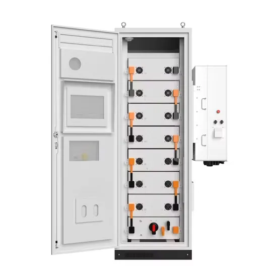
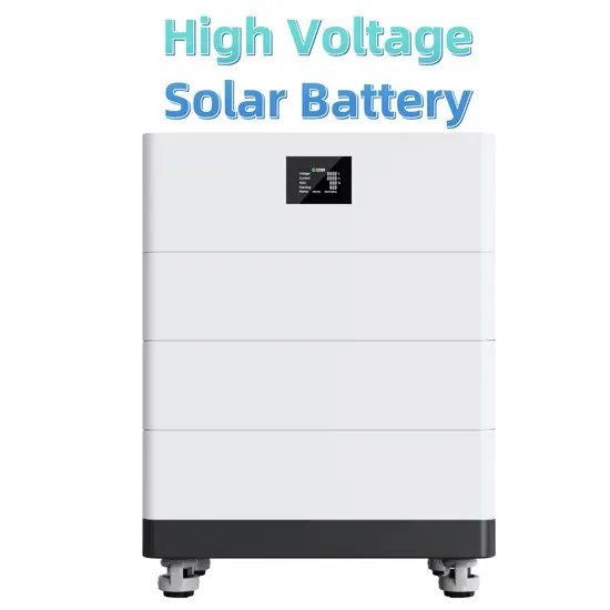
The battery management system (BMS) maintains continuous surveillance of the battery's status, encompassing critical parameters such as voltage, current, temperature, and state of charge (SOC). . The BMS checks three things before allowing a battery to charge: Temperature: Is it warm enough? Voltage: Is it within acceptable range? Current: Is the incoming current appropriate? If all three conditions are met, the battery is allowed to charge. These smart systems can handle battery packs from less than 100V up to 800V, and the supply currents are a big deal as it means that 300A. Protection is the BMS's first job.
[PDF Version]
This paper presents a double-closed-loop PWM design and control method for single-phase inverter current inner loop and voltage outer loop. By establishing the mathematical model of the single-phase inverter, the current inner loop control can obtain rapid dynamic performance, and the voltage outer. . As to the concrete topology of three-phase LCL type grid-connected inverter with damping resistance, mathematical model was deduced in detail, using method of equivalent transformation to the structure diagram, damping resistance was virtualized, mathematical model under the DQ frame that can. . losed loop control techniques for controlling the inverter working under different load or KVA ratings. The control trategy of the inverter must guarantee its output waveforms to be sinusoidal with fundamental harmonic.
[PDF Version]
Structurally, it differs from a voltage-source inverter: instead of each switching device being connected in parallel with a freewheeling diode, a current-type inverter places a reverse-blocking diode in series with each switching device. They are essential in several applications, including as power distribution networks, renewable energy systems, and. . A three phase inverter is a device that converts dc source into three phase ac output. This conversion is achieved through a power semiconductor switching topology. . These devices change direct current (DC) from batteries or panels into alternating current (AC) split across three phases for better efficiency. Let's say no neutral connected. For the wye connection, all the “negative” terminals of the inverter outputs are tied together, and for the detla connection, the inverter. . This paper compares two- and three-level AC/DC converters for three-phase industrial applications, focusing our analysis on two-level, T-type, active neutral point clamped (ANPC), neutral point clamped (NPC) and flying capacitor (FC) topologies.
[PDF Version]
The voltage from each panel adds up along the line, while the current remains constant. This configuration allows the string solar inverter to receive a higher voltage DC input, making the conversion to AC more efficient. It's a bit like several batteries connected end-to-end to. . This article provides a comprehensive analysis of voltage and current calculations for different solar panel configurations, including series, parallel, and hybrid arrangements. Each string inverter can. . At its core, a string inverter is a centralized device that converts the direct current (DC) power produced by a series-connected group of solar panels—called a string —into usable alternating current (AC) power.
[PDF Version]
At this confluence point, it monitors each PV string's current, voltage, and power. The current sensing topology enables non-isolated sensing for high-voltage systems. An IMPORTANT NOTICE at the end of this TI reference design addresses. . Discover the essentials of a solar PV array combiner box, its functions, and why monitoring is key for system performance. What Is a PV Combiner Box? A combiner box is a key DC distribution device used between PV strings and the inverter. Pick a combiner box that fits your. .
[PDF Version]
Constant Voltage Output: Inverters automatically adjust their output voltage based on load changes, ensuring a consistent voltage level. Inverter voltage typically falls into three main categories: 12V, 24V, and 48V. . They work by converting the power obtained from the DC source, which is the input source of the inverter, into AC, which is the output source of the inverter, and then distributing it to various devices that require AC sources. [1] The resulting AC frequency obtained depends on the particular device employed. Combination of pulses of different length and voltage results in a multi-stepped modified square wave, which closely matches the sine wave shape. Working Principle: Inverters use power electronics switches to mimic the AC current's changing direction, providing stable AC output. .
[PDF Version]