This guide explores how shaded solar panel, why power loss occurs, and what practical solutions can help you mitigate or avoid these losses—especially if you're designing systems for rooftops, RVs, or urban balconies. This comprehensive guide delves into various aspects of shading analysis, including its importance, types of shading, methodologies, tools for assessment, and strategies for. . When a solar panel is shaded, even partially, it can reduce or completely block the flow of sunlight to the panel, thereby reducing its efficiency in generating electricity. This is because solar panels rely on direct sunlight to generate electricity through the photovoltaic process. Understanding and conducting a thorough shading analysis is therefore vital for optimizing energy generation. Panels contain internal bypass diodes that help mitigate the effects of shading. As such, whenever a solar cell or panel does not receive sunlight — due to shading or nearby obstructions — the entire. . Whether from trees, chimneys, dust, or passing clouds, shading remains one of the most critical factors that reduce solar panel performance.
[PDF Version]
In our guide, we unpack how to wire solar panels and provide diagrams illustrating solar schematic examples for every solar setup, from residential to RV to camper van. You"ll be ready to power up your home or get. . Before diving into the splicing process, it's essential to have a basic understanding of solar PV wires. These wires are specifically designed to withstand the harsh environmental conditions typically encountered in solar installations, such as high temperatures, UV radiation, and moisture. A well-executed splice can prevent power loss, reduce the risk of electrical faults, and. . The intent of this bulletin is to clarify some of the wiring method requirements as per Section 64 Rules. This solar panel wiring guide explains different methods. . Solar panel diagrams are graphic representations of the connections you should make between each PV module and other components of the solar power system, including: Why Are They Important? Remember the saying, “Measure twice and cut once?” Detailed specifications with diagrams for reference help. . Installing a solar panel system is an efficient and sustainable way to generate electricity for your home or business. This diagram outlines the necessary connections between the. .
[PDF Version]
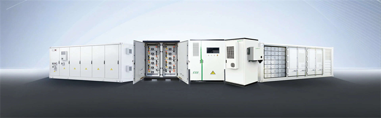
diagram for photovoltaic charging and storage sys em. Courtesy: ECOVE Environment Corp. Overview es, the load of charging piles will be secondary load. Th load curve is shown in the following figure (Fig. According. Distributed photovoltaic storage charging piles in remote rural areas can solve the problem of charging difficulties for new energy vehicles in the countryside, but these storage charging piles contain a large number of power electronic devices, and there is a risk of resonance in the system under. . In this study, an evaluation framework for retrofitting traditional electric vehicle charging stations (EVCSs) into photovoltaic-energy storage-integrated charging stations (PV-ES-I CSs) to improve green and low-carbon energy supply systems is proposed. The energy storage rate q sto per unit pile length is calculated using the equation below: (3) q sto = m ? c w T i n pile-T o u t pile / L where m ? is the mass flowrate of the circulating water; c w is th agram | Various configurations of CAES system. 1,a photovoltaic-energy storage-integrated charging station (PV-ES-I CS) is a novel component of renewable energy charging infrastructurethat combines distributed PV,battery energy storage systems,and EV charging systems.
[PDF Version]
Learn how to wire a 12V solar panel system with this straightforward wiring diagram and step-by-step guide. Always refer to the NEC code in effect or consult a licensed electrician for safety and accuracy. There are two basic approaches to connecting a grid-tied solar panel system, as shown in. . Wiring solar panels together incorrectly can lead to damaging or destroying valuable components-- it can even be life-threatening. The total output voltage and current of your array are determined by how you connect the individual PV modules to each other and to the solar inverter,charge. . Solar panel diagrams are graphic representations of the connections you should make between each PV module and other components of the solar power system, including: Why Are They Important? Remember the saying, “Measure twice and cut once?” Detailed specifications with diagrams for reference help. . A crucial part of this installation process is understanding the wiring diagram for your photovoltaic (PV) solar panels. It acts as a guide for installers, inspectors, and designers, outlining everything from the string configuration and inverters to the wiring paths and electrical connections. This will essentially serve as your map as you connect all of your components. Schematics is one of the more technical parts of DIY solar, but it doesn't have to feel like. .
[PDF Version]
The side-view diagram shows your panel at different tilt angles, with summer and winter sun paths arcing overhead. . To maximize a solar array's output, the optimal pv azimuth and tilt angle must be precisely calculated. However, this is just a baseline. Snow & Rain Factor: In colder regions, steeper tilts are better. . Our solar panel angle calculator takes the guesswork out of panel positioning, suggesting panel tilt angles based on your location's latitude and your willingness to reposition based on the sun's seasonal dance across the sky. Start by entering your location in the search box.
[PDF Version]
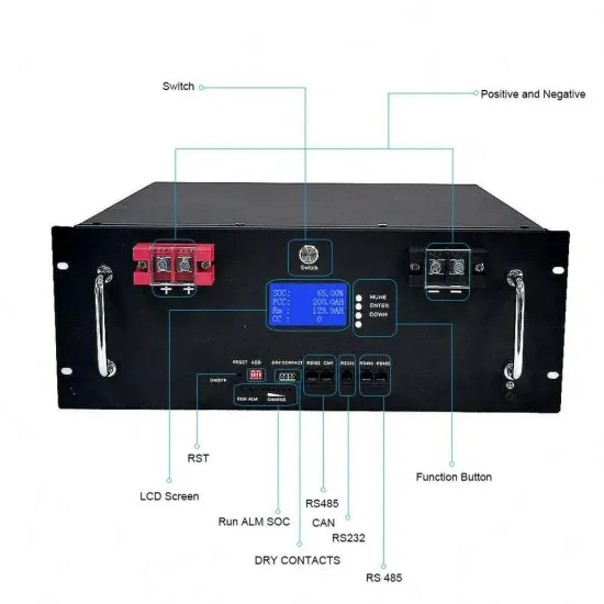
In this paper, the rough and fine grid surface of Si solar cells, CIGS solar cells, and PSCs were tested for weak light performance, and their volt-ampere characteristic curves. . For technicians who are working on photovoltaic (PV) systems, it is critical to measure and document voltage and confirm polarity. PV systems are unique electrical installations. . rization of solar cells and panels by using the 2450 or 2460, shown in Figure 1. In particular, this application note explains how to perform I-V testing from the front panel f the instrument, including how to generate graphs and save data to a USB mate the current [IS(eqV/kT – 1)], series. . Abstract: Tests to determine the performance of stand-alone photovoltaic (PV) systems and for verifying PV system design are presented in this recommended practice. This includes a cell temperature of 25°C (77°F), light intensity of 1000 Watts per square meter (similar to noon sunlight), and an atmospheric density of 1. For solar panel testing,this tool can measure a panel's output to determine if the pa el is working correctly r has wiring issues. Inspect the panels visually for any physical damage, corrosion, or dirt accumulation, 2. Measure the output voltage and current using a multimeter under standard test conditions. .
[PDF Version]